Thursday, 5 June 2014

Thrust

Thrust is a reaction force described quantitatively by Newton's second and third laws. When a system expels or accelerates mass in one direction, the accelerated mass will cause a force of equal magnitude but opposite direction on that system. The force applied on a surface in a direction perpendicular or normal to the surface is called thrust. Force, and thus thrust, is measured in the International System of Units (SI) as the newton (symbol: N), and represents the amount needed to accelerate 1 kilogram of mass at the rate of 1 metre per second squared.
In mechanical engineering, force orthogonal to the main load (such as in parallel helical gears) is referred to as thrust.
A fixed-wing aircraft generates forward thrust when air is pushed in the direction opposite to flight. This can be done in several ways including by the spinning blades of a propeller, or a rotating fan pushing air out from the back of a jet engine, or by ejecting hot gases from a rocket engine. The forward thrust is proportional to the mass of the airstream multiplied by the difference in velocity of the airstream. Reverse thrust can be generated to aid braking after landing by reversing the pitch of variable pitch propeller blades, or using a thrust reverser on a jet engine. Rotary wing aircraft and thrust vectoring V/STOL aircraft use engine thrust to support the weight of the aircraft, and vector sum of this thrust fore and aft to control forward speed.

Aerodynamic force.

Aerodynamic force is exerted on a body by the air (or some other gas) in which the body is immersed, and is due to the relative motion between the body and the gas. Aerodynamic force arises from two causes: [1][2][3]
Pressure acts locally, normal to the surface, and shear force acts locally, parallel to the surface. The net aerodynamic force over the body is due to the pressure and shear forces integrated over the total exposed area of the body.[4]
When an airfoil (or a wing) is moving relative to the air it generates an aerodynamic force, in a rearward direction at an angle with the direction of relative motion. This aerodynamic force is commonly resolved into two components:[5][6]
  • drag is the force component parallel to the direction of relative motion,
  • lift is the force component perpendicular to the direction of relative motion.
In addition to these two forces, the body may experience an aerodynamic moment also, the value of which depends on the point chosen for calculation.
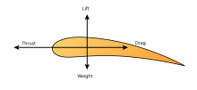
The force created by a propeller or a jet engine is called thrust and it is also an aerodynamic force (since it also acts on the surrounding air). The aerodynamic force on a powered airplane is commonly resolved into three components: thrust, lift and drag.[7][8]
The other force acting on a glider or powered airplane during flight is its weight. Weight is a body force and is not an aerodynamic force.
                                           

Airfoil

An airfoil (in American English) or aerofoil (in British English) is the shape of a wing or blade (of a propeller,rotor, or turbine) or sail as seen in cross-section.
An airfoil-shaped body moved through a fluid produces an aerodynamic force. The component of this forceperpendicular to the direction of motion is called lift. The component parallel to the direction of motion is calleddrag. Subsonic flight airfoils have a characteristic shape with a rounded leading edge, followed by a sharp trailing edge, often with asymmetric curvature of upper and lower surfaces. Foils of similar function designed with water as the working fluid are called hydrofoils.
The lift on an airfoil is primarily the result of its angle of attack and shape. When oriented at a suitable angle, the airfoil deflects the oncoming air, resulting in a force on the airfoil in the direction opposite to the deflection. This force is known as aerodynamic force and can be resolved into two components: lift and drag. Most foil shapes require a positive angle of attack to generate lift, but cambered airfoils can generate lift at zero angle of attack. This "turning" of the air in the vicinity of the airfoil creates curved streamlines which results in lower pressure on one side and higher pressure on the other. This pressure difference is accompanied by a velocity difference, via Bernoulli's principle, so the resulting flowfield about the airfoil has a higher average velocity on the upper surface than on the lower surface. The lift force can be related directly to the average top/bottom velocity difference without computing the pressure by using the concept of circulation and the Kutta-Joukowski theorem.[1][2][3][4]

Angle of Attack

Angle of attack (AOA, or \alpha (Greek letter alpha)) is the angle between a reference line on a body (often the chord line of an airfoil) and the vector representing the relative motion between the body and the fluid through which it is moving.[1] Angle of attack is the angle between the body's reference line and the oncoming flow. This article focuses on the most common application, the angle of attack of a wing or airfoil moving through air.
In aerodynamics, angle of attack specifies the angle between the chord line of the wing of a fixed-wing aircraft and the vector representing the relative motion between the aircraft and the atmosphere. Since a wing can have twist, a chord line of the whole wing may not be definable, so an alternate reference line is simply defined. Often, the chord line of the root of the wing is chosen as the reference line. Another choice is to use a horizontal line on the fuselage as the reference line (and also as the longitudinal axis).[2] Some authors[3][4] do not use an arbitrary chord line, but use thezero lift axis instead — zero angle of attack corresponds to zero coefficient of lift.
Some British authors have used the term angle of incidence instead of angle of attack. However, this can lead to confusion with the term riggers' angle of incidence meaning the angle between the chord of an aerofoil and some fixed datum in the aeroplane.[5]
                                                

Lift-induced drag

Lift-induced drag[edit]

Main article: Lift-induced drag
Induced drag vs.lift[18][19]
Lift-induced drag (also called induced drag) is drag which occurs as the result of the creation of lift on a three-dimensional lifting body, such as the wing or fuselage of an airplane. Induced drag consists of two primary components, including drag due to the creation of vortices (vortex drag) and the presence of additional viscous drag (lift-induced viscous drag). The vortices in the flow-field, present in the wake of a lifting body, derive from the turbulent mixing of air of varying pressure on the upper and lower surfaces of the body, which is a necessary condition for the creation of lift.
With other parameters remaining the same, as the lift generated by a body increases, so does the lift-induced drag. For an aircraft in flight, this means that as the angle of attack, and therefore the lift coefficient, increases to the point of stall, so does the lift-induced drag. At the onset of stall, lift is abruptly decreased, as is lift-induced drag, but viscous pressure drag, a component of parasite drag, increases due to the formation of turbulent unattached flow on the surface of the body.

Parasitic drag[edit]

Main article: parasitic drag
Parasitic drag (also called parasite drag) is drag caused by moving a solid object through a fluid. Parasitic drag is made up of multiple components including viscous pressure drag (form drag), and drag due to surface roughness (skin friction drag). Additionally, the presence of multiple bodies in relative proximity may incur so calledinterference drag, which is sometimes described as a component of parasitic drag.
In aviation, induced drag tends to be greater at lower speeds because a high angle of attack is required to maintain lift, creating more drag. However, as speed increases the induced drag becomes much less, but parasitic drag increases because the fluid is flowing more quickly around protruding objects increasing friction or drag. At even higher speeds in the transonic, wave drag enters the picture. Each of these forms of drag changes in proportion to the others based on speed. The combined overall drag curve therefore shows a minimum at some airspeed - an aircraft flying at this speed will be at or close to its optimal efficiency. Pilots will use this speed to maximizeendurance (minimum fuel consumption), or maximize gliding range in the event of an engine failure.

Power curve in aviation[edit]

The power curve: form and induced drag vs. airspeed
The interaction of parasitic and induced drag vs. airspeed can be plotted as a characteristic curve, illustrated here. In aviation, this is often referred to as the power curve, and is important to pilots because it shows that, below a certain airspeed, maintaining airspeed counterintuitively requires more thrust as speed decreases, rather than less. The consequences of being "behind the curve" in flight are important and are taught as part of pilot training. At the subsonic airspeeds where the "U" shape of this curve is significant, wave drag has not yet become a factor, and so it is not shown in the curve.

Wave drag in transonic and supersonic flow[edit]

Qualitative variation in Cd factor with Mach number for aircraft
Main article: wave drag
Wave drag (also called compressibility drag) is drag which is created by the presence of a body moving at high speed through a compressible fluid. In aerodynamics, Wave drag consists of multiple components depending on the speed regime of the flight.
In transonic flight (Mach numbers greater than about 0.8 and less than about 1.4), wave drag is the result of the formation of shockwaves on the body, formed when areas of local supersonic (Mach number greater than 1.0) flow are created. In practice, supersonic flow occurs on bodies traveling well below the speed of sound, as the local speed of air on a body increases when it accelerates over the body, in this case above Mach 1.0. However, full supersonic flow over the vehicle will not develop until well past Mach 1.0. Aircraft flying at transonic speed often incur wave drag through the normal course of operation. In transonic flight, wave drag is commonly referred to as transonic compressibility drag. Transonic compressibility drag increases significantly as the speed of flight increases towards Mach 1.0, dominating other forms of drag at these speeds.
In supersonic flight (Mach numbers greater than 1.0), wave drag is the result of shockwaves present on the body, typicallyoblique shockwaves formed at the leading and trailing edges of the body. In highly supersonic flows, or in bodies with turning angles sufficiently large, unattached shockwaves, or bow waves will instead form. Additionally, local areas of transonic flow behind the initial shockwave may occur at lower supersonic speeds, and can lead to the development of additional, smaller shockwaves present on the surfaces of other lifting bodies, similar to those found in transonic flows. In supersonic flow regimes, wave drag is commonly separated into two components, supersonic lift-dependent wave drag and supersonic volume-dependent wave drag.
The closed form solution for the minimum wave drag of a body of revolution with a fixed length was found by Sears and Haack, and is known as the Sears-Haack Distribution. Similarly, for a fixed volume, the shape for minimum wave drag is the Von Karman Ogive.
Busemann's Biplane is not, in principle, subject to wave drag at all when operated at its design speed, but is incapable of generating lift.
Air Speed Record
An air speed record is the highest airspeed attained by an aircraft of a particular class. The rules for all official aviation records are defined by Fédération Aéronautique Internationale (FAI),[1] which also ratifies any claims. Speed records are divided into multiple classes with sub-divisions. There are three classes of aircraft: landplanes, seaplanes, and amphibians; then within these classes, there are records for aircraft in a number of weight categories. There are still further sub-divisions for piston-engined, turbojet, turboprop, and rocket-engined aircraft. Within each of these groups, records are defined for speed over a straight courThe Lockheed SR-71 Blackbird holds the official Air Speed Record for a manned airbreathing jet aircraft with a speed of 3,530 km/h (2,193 mph). It was capable of taking off and landing unassisted on conventional runways. The record was set on 28 July 1976 by Eldon W. Joersz and George T. Morgan Jr. near Beale Air Force Base,California, US.[42]se and for closed circuits of various sizes carrying various payloads.
Although the official record for fastest piston-engined aeroplane in level flight is held by a Grumman F8F Bearcat, the Rare Bear, with a speed of 528.31 mph (850.24 km/h), the unofficial record for fastest piston-engined aeroplane in level flight is a held by a British Hawker Sea Fury at 547 mph (880 km/h). Whereas these were both demilitarised, modified fighters, the fastest piston-engined aeroplane in stock (original, factory-built) condition was the German Dornier Do 335 Pfeil, with a maximum speed of 474 mph (765 km/h) in level flight. The unofficial record for fastest piston-engined aeroplane (not in level flight) is held by a Supermarine Spitfire Mk IXX, which was calculated to have achieved a speed of 690 mph (1,110 km/h, Mach 0.96) in a dive on 5 February 1952.


Helicopter flight controls

A helicopter pilot manipulates the helicopter flight controls in order to achieve controlled aerodynamic flight.[1] The changes made to the flight controls are transmitted mechanically to the rotor, producing aerodynamic effects on the helicopter's rotor blades which allow the helicopter to be controlled. For tilting forward and back (pitch), or tilting sideways (roll), the angle of attack of the main rotor blades is altered cyclically during rotation, creating differing amounts of lift at different points in the cycle. For increasing or decreasing overall lift, the angle of attack for all blades is collectively altered by equal amounts at the same time resulting in ascents, descents, acceleration and deceleration.
A typical helicopter has three separate flight control inputs. These are the cyclic stick, the collective lever, and the anti-torque pedals.[2] Depending on the complexity of the helicopter, the cyclic and collective may be linked together by a mixing unit, a mechanical or hydraulic device that combines the inputs from both and then sends along the "mixed" input to the control surfaces to achieve the desired result. The manual throttle may also be considered a flight control because it is needed to maintain rotor speed on smaller helicopters without governors. The governors also help the pilot control the collective pitch on the helicopters main rotors, to keep a stable, more accurate flight.
                                               Helicopter controls diagram.svg

Controls

Cyclic

The cyclic control is usually located between the pilot's legs and is commonly called the cyclic stick or just cyclic. On most helicopters, the cyclic is similar in appearance to a joystick in a conventional aircraft. The control is called the cyclic because it changes the pitch angle of the rotor blades cyclically. That is, the pitch or feathering angle of the rotor blades changes depending upon their position as they rotate around the hub so that all blades will have the same incidence at the same point in the cycle. The change in cyclic pitch has the effect of changing the angle of attack and thus the lift generated by a single blade as it moves around the rotor disk. This in turn causes the blades to fly up or down in sequence, depending on the changes in lift affecting each individual blade.
The result is to tilt the rotor disk in a particular direction, resulting in the helicopter moving in that direction. If the pilot pushes the cyclic forward, the rotor disk tilts forward, and the rotor produces a thrust vector in the forward direction. If the pilot pushes the cyclic to the right, the rotor disk tilts to the right and produces thrust in that direction, causing the helicopter to move sideways in a hover or to roll into a right turn during forward flight, much as in a fixed wing aircraft.
On any rotor system there is a delay between the point in rotation where a change in pitch is introduced by the flight controls and the point where the desired change is manifest in the rotor blade's flight. This difference is caused by phase lag, often confused with gyroscopic precession. A rotor is an oscillatory system that obeys the laws governing vibration which, depending on the rotor system, may resemble the behaviour of a gyroscope.

Collective

The collective pitch control, or collective lever, is normally located on the left side of the pilot's seat with an adjustable friction control to prevent inadvertent movement. The collective changes the pitch angle of all the main rotor blades collectively (i.e., all at the same time) and independent of their position. Therefore, if a collective input is made, all the blades change equally, and the result is the helicopter increases or decreases its total lift derived from the rotor. In level flight this would cause a climb or descent, while with the helicopter pitched forward an increase in total lift would produce an acceleration together with a given amount of ascent.
The collective pitch control in a Boeing CH-47 Chinook is called a "Thrust Control", but it serves the exact same purpose, except that it controls two rotor systems and applies differential collective pitch into the two rotor systems.[3]

Anti-torque pedals

The anti-torque pedals are located in the same position as the rudder pedals in an airplane, and serve a similar purpose, namely to control the direction in which the nose of the aircraft is pointed. Application of the pedal in a given direction changes the pitch of the tail rotor blades, increasing or reducing the thrust produced by the tail rotor and causing the nose to yaw in the direction of the applied pedal. The pedals mechanically change the pitch of the tail rotor altering the amount of thrust produced.

Throttle

Helicopter rotors are designed to operate at a specific rotational speed. The throttle controls the power produced by the engine, which is connected to the rotor by a transmission. The purpose of the throttle is to maintain enough engine power to keep the rotor speed within allowable limits in order to keep the rotor producing enough lift for flight. In many helicopters, the throttle control is a single or dual motorcycle-style twist grip mounted on the collective control (rotation is opposite of a motorcycle throttle), while some multi-engine helicopters have power levers.
In many piston engine-powered helicopters, the pilot manipulates the throttle to maintain rotor speed. Turbine engine helicopters, and some piston helicopters, use governors or other electro-mechanical control systems to maintain rotor speed and relieve the pilot of routine responsibility for that task. (There is normally also a manual reversion available in the event of a governor failure.)